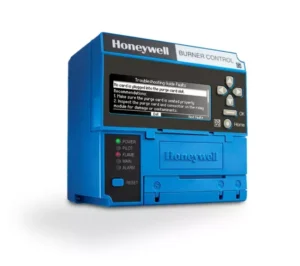
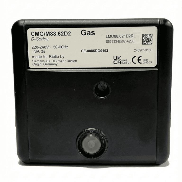
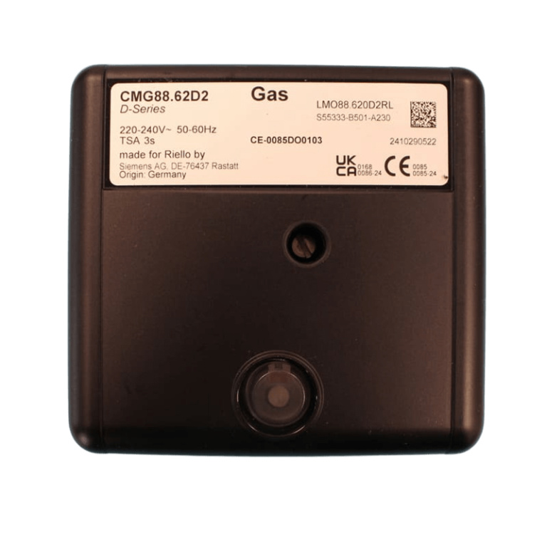
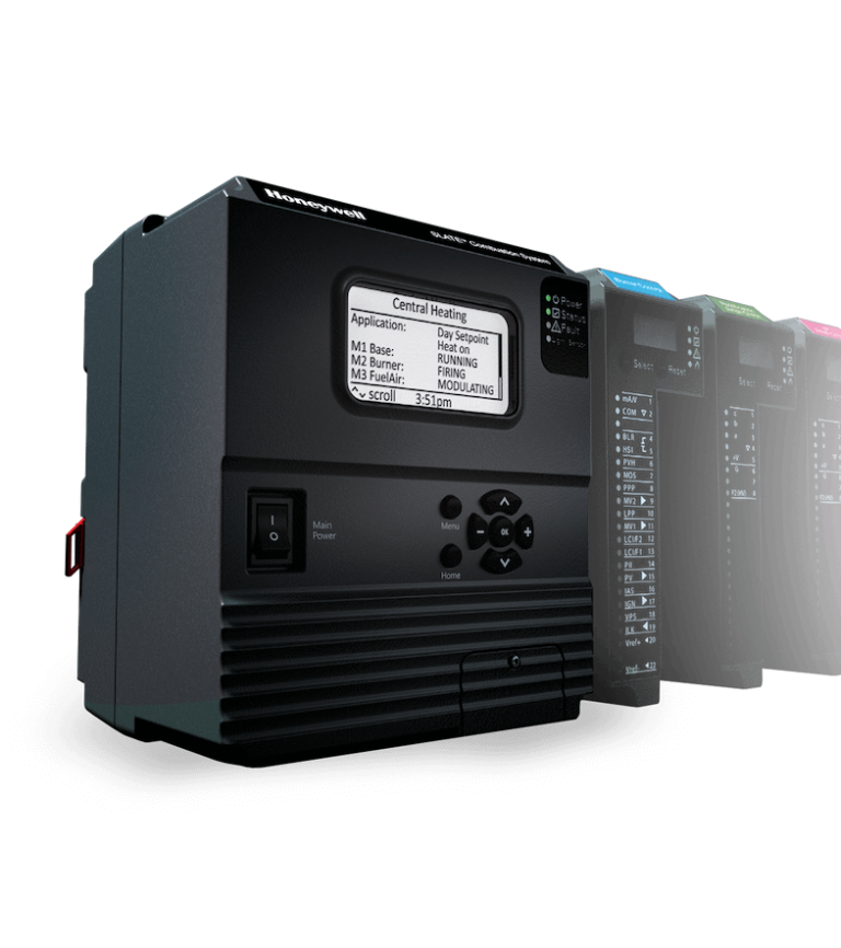
The Honeywell 7800 SERIES is a modular burner-control family for automatic sequencing, flame supervision and fault diagnostics. Select the relay module for the required burner sequence, then match its flame amplifier, detector and mounting components.
Choose the Relay Module
The full ordering code determines the power supply, purge sequence, pilot operation and interlock arrangement. The following configurations illustrate the principal differences:
| Relay module | Power supply | Control / interlocks | Display |
|---|---|---|---|
| RM7800L1012 | 120 V AC, 50/60 Hz | Modulating; low- and high-fire proving; lockout interlocks | Keyboard display included |
| RM7840L1018 | 120 V AC, 50/60 Hz | Modulating; low- and high-fire proving; lockout interlocks | Dust cover; display optional |
| RM7800G1018 | 120 V AC, 50/60 Hz | Modulating; low-fire proving; running interlocks | Keyboard display included |
| RM7840G1014 | 120 V AC, 50/60 Hz | Modulating; low-fire proving; running interlocks | Dust cover; display optional |
| RM7895A1014 | 120 V AC, 50/60 Hz | On/off with prepurge; intermittent pilot | Optional |
| EC7895A1010 | 220–240 V AC, 50/60 Hz | On/off with prepurge; intermittent pilot | Optional |
For RM7800L1012 and RM7840L1018, pilot flame-establishing time is 4 or 10 seconds and main flame-establishing time is 10 or 15 seconds. Prepurge is selected with the ST7800 timing card; postpurge is 15 seconds. The G versions have a different pilot/main-valve sequence and running-interlock arrangement.
Flame Amplifier and Detector Pairing
| Detection | Amplifier | Detector |
|---|---|---|
| UV Minipeeper | R7849A / R7849B | C7027A, C7035A, C7044A |
| Self-checking UV | R7861A | C7061A |
| Infrared | R7848A / R7848B | C7015 |
| Optical | R7851B | C7927 / C7962 |
R7849B Ampli-Check monitors the amplifier; it does not make a C7027A or C7035A detector dynamically self-checking. These Minipeeper detectors require the burner to cycle off at least once every 24 hours. For continuous UV supervision, Honeywell specifies a self-checking detector/amplifier combination such as C7061A with R7861A. Flame-failure response time is determined by both the amplifier and relay module.
System Components
- Q7800 wiring subbase: provides the field-wiring interface.
- Flame amplifier and matching detector: selected as a compatible pair.
- ST7800 purge timer: required by the RM7800/RM7840 and RM/EC7895 configurations shown above; it is not a universal requirement for every 7800-series control.
- Keyboard display: sequence status, flame signal and fault information; standard or optional as shown in the model table.
- Communication: compatible display/interface modules provide Modbus integration.
Specify Your Configuration
Quote the complete relay-module code and the amplifier, purge-card and display references required. State whether the enquiry is for the relay module alone or a complete assembly. Compare C7027A, C7035A and C7061A1020 detector options.